
NORELEM FRANCE
France

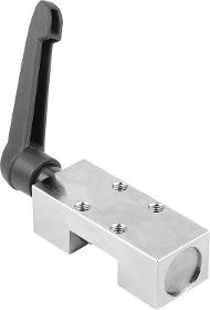
Housing steel. Clamping lever plastic. Threaded spindle grade 12.9. Version Housing nickelplated. Clamping lever, spindle black oxidised. Note Manually operated clamping elements for static clamping tasks. Manual clamping process using the freely adjustable clamping lever. The floating clamp ensure symmetrical application of force onto the rail. Up to 50,000 static clamping cycles (B10d value). In general, a friction connection is created between the clamping element and the the linear guide on the open faces of the profile guide rail so that the ball guide tracks are not damaged. The retaining force is tested on an oil smeared profile guide rail. An adapter plate, dependent on the type of carriage used, is required for height adjustment.
NORELEM FRANCE
France
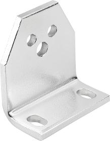
The angle bracket enables easy mounting of the clamping elements directly on the machine component. The bore D2 serves to hold the clamping element. The clamping element can be mounted on the front or rear of the bracket. The bores D3 enable the bracket to used for other applications.
NORELEM FRANCE
France
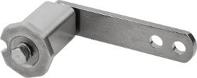
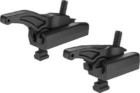
Housing 1.4308 stainless steel, from size 5 1.4301. Clamping arm 1.4301 stainless steel. Buffer natural rubber. Screw stainless steel A2. Version Housing and lever arm bright. Screw ISO 4017, grade 70, bright. Note Clamping element with integrated highly elastic, shaperetaining natural rubber buffer. Together with a chain tensioner set, sprocket set or a tension pulley, the clamping element makes a readytoinstall tensioning unit suitable for tensioning chain and belt drives. Suitable for both tensioning directions. The clamping elements are maintenancefree and tearoff resistant. The clamping element is fastened to the machine component through a bore. If necessary, a heavyduty dowel pin can be inserted in the positioning notch “P” for torque support.
IGUS® GMBH
Germany
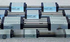
DryLin® T linear guide systems were specially developed for applications in automation and handling systems. The design objective was a rugged linear guide for application in the most diverse - and also extreme - environments. They have the same dimensions as most recirculating ball bearing guides. Technical data Gliding elements: Maintenance-free Material: iglidur® J * Max. surface speed: 15 m/s Operating temperature: -40°C to +90°C *Other materials on request 1 Profile rail and base body of the carriage made of aluminum. The rail is hard-anodized, the aluminum base body of the carriage is clear anodized. 2 Six gliding elements made of iglidur® J serve as guide bearings, which are positioned opposite to each other in pairs and make up 3 guide bearings. 3 Alternatively, bearing clearance is continuously adjustable 4 All steel parts are stainless steel 5 The lid is made of solid plastic or stainless steel DryLin® T - Technical data DryLin® T - Clearance adjustment DryLin® TWBM hand clamp DryLin® T - Design rules DryLin® T - Automatic clearance adjustment DryLin® linear guide systems in the cleanroom DryLin® T - Applications DryLin® T - System design DryLin® T - Installation videos System selection & service life calculation DryLin® T - Adjustable clearance The DryLin® T standard version is supplied preset and can be put into operation at once. The user can also manually adjust or fine-tune the clearance of the linear guide. The individual adjustment for your application, as well as the potential to respond to uneven screw surfaces through specific clearance allowance. DryLin® T - Adjustable clearance DryLin® T - Automatic DryLin® T carriages of the automatic version have a mechanism that automatically adjusts the bearing clearance after removal of the preload key. In case a bearing clearance of more than 0.13 mm has to be adjusted during operation, the bearing clearance automatically resets itself when the carriage is completely unloaded. DryLin® T - Automatic DryLin® TW-HKA manual clamp The manual clamp has been developed for simple tasks. The creep behavior of the clamped plastic causes a slackening in clamping force over time (up to 70%). Therefore safety-related parts should not be clamped. Please approach our applications consultant if you require other options for the clamping. DryLin® T - Manual clamping Drylin® T - Heavy Duty This series is used for the most extreme conditions such as dirt, adhesive residues, chips, mud, etc. The plastic gliding elements made of iglidur® J are fixed in the lid and are therefore non-detachable. This system is compatible with many standard commercial recirculating ball bearing systems and is available in the following sizes: TW-01-20, TW-01-25 and TW-01-30. DryLin® T Heavy Duty DryLin® T - Low-profile guide The clearance is not adjustable for the DryLin® T low profile guide rails. The gliding elements are mounted with positive fit in the chromated zinc carriage. This simple and effective design enables guides that are rugged and low-priced at the same time. DryLin® T - Low-profile guide DryLin® T - Compact linear guide This compact linear guide is suitable for rugged use (without clearance adjustment). This system has a slim design and the same dimensions as conventional recirculating ball bearing systems. The plastic gliding elements made of iglidur® J are fixed in the lid and are therefore undetachable. Suitable for DryLin® T guide rail of installation size 20. DryLin® T - Compact linear guide DryLin® TWBM - Manual clamping with high holding force This manual clamping is designed for a long-lasting high holding force of up to 500 N per clamping element. DryLin® TWBM hand clamp DryLin® T clamping elements for rail guide DryLin® T clamping elements for fast positioning by hand or with pneumatics. DryLin® T clamping element DryLin® T linear guide systems were specially developed for applications in automation and handling systems. The design objective was a rugged linear guide for application in the most diverse - and also extreme - environments. They have the same dimensions as most recirculating ball bearing guides. Technical data Gliding elements: Maintenance-free Material: iglidur® J * Max. surface speed: 15 m/s Operating temperature: -40°C to +90°C *Other materials on request 1 Profile rail and base body of the carriage made of aluminum. The rail is hard-anodized, the aluminum base body of the carriage is clear anodized. 2 Six gliding elements made of iglidur® J serve as guide bearings, which are positioned opposite to each other in pairs and make up 3 guide bearings. 3 Alternatively, bearing clearance is continuously adjustable 4 All steel parts are stainless steel 5 The lid is made of solid plastic or stainless steel Advantages: 100 % lubricant-free Adjustable bearing clearance Automatic clearance adjustment High static load capacity Service life up to 50,000 km without lubrication High dirt resistance Low vibration and low noise When not to use ? When you want to save installation space drylin® N drylin® W When you need a pure stainless steel solution drylin® W drylin® R When you want to construct as economical as possible drylin® N drylin® W

IGUS® GMBH
Germany
drylin® W - Advantages Dirt-resistant Weight saving Lubrication-free High speed Silent and light weight drylin® W - Advantages drylin® W - technical properties The technical properties of the drylin® W profile guide system Technical properties drylin® W - configuration Find the right profile guide system in 4 simple steps with the system and life calculation. drylin® W - configuration Single rail and housing bearing - round Sizes: 10 mm, 16 mm, 20 mm and 25 mm DryLin® W single rail and housing bearing - round Single rail and housing bearing - angular Sizes: 6 mm, 10 mm, 16 mm and 20 mm DryLin® W single rail and housing bearing - angular double rail, round Sizes: 10 mm (rail width 40 mm, 74 mm and 120 mm), 16 mm (rail width 58 mm), 20 mm (rail width 82 mm) and 25 mm (rail width 120 mm) DryLin® W double rail Guide carriage, assembled Sizes: 10 mm, 16 mm, 20 mm and 25 mm DryLin® W guide carriage, assembled double rail, square Sizes: 06 mm (rail width 30 mm), 10 mm (rail width 40 mm and 74 mm) and 16 mm (rail width 58 mm) drylin® W double rail, square Mono-slide guide carriage Size: 10 mm Mono-Slide guide Single rail and housing bearing - round, adjustable Sizes: 10 mm, 16 mm and 20 mm Linear Guides with “Turn-To-Fit” Hybrid bearing WJRM drylin® roller bearings - Roll and glide for easy movement. drylin® W hybrid bearing | roller bearing hybrid bearing double WJRM drylin® double roller bearing - Roll and glide for easy movement. drylin® W hybrid bearing double Double rail, reduced weight Sizes: 6 mm (rail width 30 mm), 10 mm (rail width 40 mm and 80 mm) DryLin® W double rail, reduced weight Hybrid carriage with rollers Size: 10, 16 mm DryLin® W hybrid carriage with rollers Stainless steel guide V4A, individual Size: 20 mm DryLin® W stainless steel guide V4A - individual Stainless steel guide V4A - double DryLin® W stainless steel guide V4A - double drylin® W slider rails/carriages drylin® W rail profiles with 3/8" threads, complete rails with Ø 10 mm through bore, with/without hand clamps DryLin® W double rail, square Gliding elements For round and angular rails. DryLin® W - Gliding elements Manual clamp Developed for simple positioning tasks. DryLin® W - Manual clamp Digital measuring system With immediate digital indication of position. DryLin® W - Digital measuring system Hand clamp for higher forces Designed for positioning tasks with higher forces. DryLin® W hand clamp for higher forces DryLin® WKMEX digital measuring system with external output drylin® WKMEX measuring system with external output DryLin® SLW - the compact* Spindle-lift tables The extremely thin unit is based on a DryLin® W profile system, and its entire length is supported. This design offers an extremely high torsional stiffening simultaneously with compact dimensions. DryLin® SLW - Compact DryLin® ZLW Toothed belt axis For quick positioning of small loads. DryLin® ZLW - Toothed belt axis Single rail and housing bearing - round Sizes: 10 mm, 16 mm, 20 mm and 25 mm DryLin® W single rail and housing bearing - round Single rail and housing bearing - angular Sizes: 6 mm, 10 mm, 16 mm and 20 mm DryLin® W single rail and housing bearing - angular double rail, round Sizes: 10 mm (rail width 40 mm, 74 mm and 120 mm), 16 mm (rail width 58 mm), 20 mm (rail width 82 mm) and 25 mm (rail width 120 mm) DryLin® W double rail Guide carriage, assembled Sizes: 10 mm, 16 mm, 20 mm and 25 mm DryLin® W guide carriage, assembled double rail, square Sizes: 06 mm (rail width 30 mm), 10 mm (rail width 40 mm and 74 mm) and 16 mm (rail width 58 mm) drylin® W double rail, square Mono-slide guide carriage Size: 10 mm Mono-Slide guide Single rail and housing bearing - round, adjustable Sizes: 10 mm, 16 mm and 20 mm Linear Guides with “Turn-To-Fit” Hybrid bearing WJRM drylin® roller bearings - Roll and glide for easy movement. drylin® W hybrid bearing | roller bearing hybrid bearing double WJRM drylin® double roller bearing - Roll and glide for easy movement. drylin® W hybrid bearing double Double rail, reduced weight Sizes: 6 mm (rail width 30 mm), 10 mm (rail width 40 mm and 80 mm) DryLin® W double rail, reduced weight Hybrid carriage with rollers Size: 10, 16 mm DryLin® W hybrid carriage with rollers Stainless steel guide V4A, individual Size: 20 mm DryLin® W stainless steel guide V4A - individual Stainless steel guide V4A - double DryLin® W stainless steel guide V4A - double drylin® W slider rails/carriages drylin® W rail profiles with 3/8" threads, complete rails with Ø 10 mm through bore, with/without hand clamps DryLin® W double rail, square Gliding elements For round and angular rails. DryLin® W - Gliding elements Manual clamp Developed for simple positioning tasks. DryLin® W - Manual clamp Digital measuring system With immediate digital indication of position. DryLin® W - Digital measuring system Hand clamp for higher forces Designed for positioning tasks with higher forces. DryLin® W hand clamp for higher forces DryLin® WKMEX digital measuring system with external output drylin® WKMEX measuring system with external output DryLin® SLW - the compact* Spindle-lift tables The extremely thin unit is based on a DryLin® W profile system, and its entire length is supported. This design offers an extremely high torsional stiffening simultaneously with compact dimensions. DryLin® SLW - Compact DryLin® ZLW Toothed belt axis For quick positioning of small loads. DryLin® ZLW - Toothed belt axis drylin® W - Advantages Dirt-resistant Weight saving Lubrication-free High speed Silent and light weight drylin® W - Advantages drylin® W - technical properties The technical properties of the drylin® W profile guide system Technical properties drylin® W - configuration Find the right profile guide system in 4 simple steps with the system and life calculation. drylin® W - configuration
NORELEM FRANCE
France
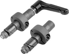
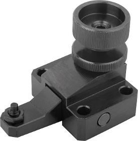
The screw is tightened or the clamping lever is turned to expand the two wedges in the hole. The infinitely adjustable shaft collar enables one or more stop elements with various thicknesses to be securely fixated. Application: These clamping pins are perfect for fixing standard stop elements with various thicknesses to hole grid boards / welding tables with hole Ø 16 mm or 28 mm. Advantages: Infinitely adjustable clamping range of 0-36 mm and 0-75 mm. Not affected by the diameter or surface quality of the bore (up to H12). Clamping range can be easily preset using the scale. Gentle clamping in the bore. Pull-down effect even with thin table material (≥8 mm or ≥4 mm). Compatible with conventional stop elements.
NORELEM FRANCE
France
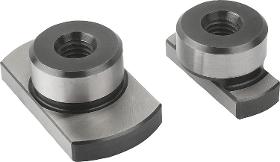
Body carbon steel, black oxidised. Jaw carbon steel, tempered, black oxidised. Note: The adjustable toe clamp is used together with the rack plate CL.

NORELEM FRANCE
France
Hook clamps and clamping screw carbon steel, tempered.
NORELEM FRANCE
France
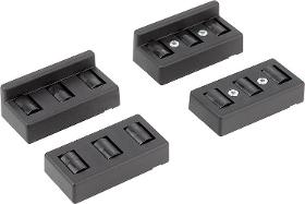
Housing glassbead reinforced polyamide. Rollers POM. Screws steel. Version Housing and rollers black. Screws electro zincplated. Note The roller elements are ideal for constructing roller conveyors in any length and width. Suitable for aluminium profiles types B and I. The sprung guide tabs underneath universally match slots sized 8 and 10. Mounting Form A Insert the lower housing part with rollers into the aluminium profile slot. Set the spread pins on the upper housing part into the lower housing part and press down. The spread pins expand the clamps and locks the roller element in the slot. Mounting Form B Insert the lower housing part with rollers into the aluminium profile slot. Set the upper housing part on top and press down. Knocking or screwing the screws in locks and clamps the roller element in the slot.
NORELEM FRANCE
France
Case-hardened, black oxidised and ground. Note: To align fixtures and clamping elements on subplates and palettes with location holes. They can be mounted in holes or slots.
NORELEM FRANCE
France
Workpiece supports are for supporting overhanging workpiece parts to prevent vibrations and bending during machining. They should not be subjected to strong forces from a clamping element and are not intended as supports under a clamping point.
NORELEM FRANCE
France
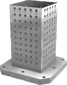
Grid spacing 50 ±0.02 mm. Tombstones with grid holes are used on horizontal machining centres. The alphanumerically labelled grid holes guarantee a defined assignment of clamping elements by repeat setups. The tombstones conform to machine tables for machine tools acc. to DIN 55201 and JIS 6337-1980. Please order locating pins for positioning subplates on machine tables acc. to DIN 55201 separately. Please order protection plugs to plug unused grid holes separately. Ring bolts for hoisting are supplied. Other dimensions available on request. Drawing reference: 1) grid hole 2) hole for DIN 912 cap screw (D3/D4)
NORELEM FRANCE
France
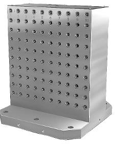
Grid spacing 50 ±0.02 mm. Tombstones with grid holes are used on horizontal machining centres. The alphanumerically labelled grid holes guarantee a defined assignment of clamping elements by repeat setups. The tombstones conform to machine tables for machine tools acc. to DIN 55201 and JIS 6337-1980. Please order locating pins for positioning subplates on machine tables acc. to DIN 55201 separately. Please order protection plugs to plug unused grid holes separately. Ring bolts for hoisting are supplied. Other dimensions available on request. Drawing reference: 1) grid hole 2) hole for DIN 912 cap screw (D3/D4)
NORELEM FRANCE
France
We recommend using a lubricating paste to reduce wear to the adjustment screw. Risers are available to increase the height of the power clamp. Supplied with clamping element, support element, DIN 508 slot key and grade 12.9 bolt. Application: The height of the clamping arm can be infinitely adjusted using the adjustment screw and the workpiece can then be clamped. Advantages: Very high retaining forces of 22–49 kN. Low height. Simple element assembly. Enables very fast, simple clamping. Infinitely adjustable height and length. Use in 12-28 mm T-slots or M10, M12, M16, M20 grid systems. Thrust pad available in smooth and serrated versions.

NORELEM FRANCE
France
The indexing and clamping grips enable the positioning, securing and clamping of diverse positioning elements with just one product. Indexing is carried out using the indexing pin and the item is clamped using the end face of the sleeve. A protruding signal button means that the indexing pin is not completely extended.
RHIMEX.COM
Netherlands
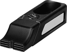
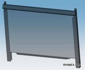
This OHB roller blind can be infinitely adjusted in both directions. That is why the grab bar is equipped with two clamping elements, which are placed laterally on straight (Irollo) or Ubent bars (Urollo). The clamping elements tilt so that the roller blind remains in the selected position. Can be placed in any desired position without causing friction Delivery time only 4 weeks Different screw widths possible
1ST MACHINE TOOL ACCESSORIES
United Kingdom
Reduce your set-up times by more than 90%. Self-clamping mechanism, constant air not required Made from heat treated refined steel Positioning slots allow for indexing by 90° Created for use on CNC machining centres, the V-Tech Zero Point system’s unique design guarantees the secure and precise clamping of workpieces, even under tough conditions. The pneumatic, quick change and ZERO POINT clamp features compact dimensions, extraordinarily high clamping force and is made from top quality materials. V-Tech clamping and location elements can be purchased individually to easily adapt workholding and fixtures for lightning fast changeovers. V-Tech receivers are also available as a . Each V-Tech receiver provides 24KN of clamping force and has positioning slots to allow for indexing by 90 degrees. The self-clamping mechanism means the force is still applied after the air has been disconnected.

Do you sell or make similar products?
Sign up to europages and have your products listed
1ST MACHINE TOOL ACCESSORIES
United Kingdom
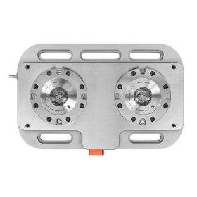
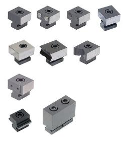
Maximise your machining envelope High precision and high clamping force Wide range of accessories for flexibility Clamp single large or multiple small workpieces Workstops to suit OK-Vise Multi-Rail. Multi-Rail can accommodate OK-Vise clamps, stops, parallels and other accessories to clamp multiple components and maximise your milling work area. All the clamping and location elements on the rail can be positioned according to the size and shape of the workpieces to swiftly adapt from clamping multiple small workpieces to clamping single large workpieces. These stops are available in a range of styles and applications.
Results for
Clamping elements - Import exportNumber of results
19 ProductsCompany type