VENJAKOB MASCHINENBAU GMBH & CO KG
Germany
Manufacturer/ Producer

VENJAKOB MASCHINENBAU GMBH & CO KG
Germany
high-performance curing of 3d workpieces Venjakob has introduced innovative LED technology to 3D curing. The lower thermal stress of the workpieces and optimized energy consumption are compelling advantages. The air in the factory is not contaminated with ozone – as is the case with conventional UV technology – and the longer lifetime of the LED lamps improves the energy balance. System benefits BLUE COMPETENCE

VENJAKOB MASCHINENBAU GMBH & CO KG
Germany
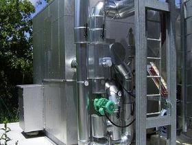
The adsorption system (AD) from Venjakob Umwelttechnik serves to concentrate exhaust air flows containing low concentrations of pollutants, and is particularly suitable for removing extremely low to medium concentrations of solvent-based pollutants (VOCs). This machine is characterized by: During the adsorption process, the pollutants are physically retained on the surface of a solid material (e.g. activated carbon, zeolite). The pollutants are then removed /desorbed from the zeolite by means of a small, hot stream of air. Afterwards, the flow of exhaust air from the desorption process is cleaned by means of an exhaust air cleaning system (TI, RTO, CTO). By reducing the volume and by increasing the concentration, the operating costs of the downstream exhaust gas purification system can be kept very low and make autothermal operation possible among other things The rotor is mounted vertically on a shaft with bearing and rotated slowly in the air flow. During rotation, the adsorption and desorption take place simultaneously in separate chambers with cooling on a hydrophobic (water-repellent) incombustible zeolite material. For tough applications, versions can be provided with a removable wear layer and / or higher temperatures of up to 300 ° C for desorption. Two containers are operated alternately. While one of the containers is adsorbing, the other container can be desorbed The adsorption process can be used for smoothing pollutant concentration peaks. If pollutant peaks occur during a process that could lead to a potentially explosive mixture (> 25% lower explosion limit), they cannot be introduced into an incinerator. However, the pollutants may be temporarily stored in an adsorber and then be released during the desorption phase. In certain situations, the installation of an additional fixed bed adsorber (molecular sieve) may further enhance the process (safety, operating costs).
VENJAKOB MASCHINENBAU GMBH & CO KG
Germany
For its exhaust gas purification systems, Venjakob Umwelttechnik offers heat exchanger systems for utilizing the waste heat. These are characterized by: We build complete heat exchanger systems for heating water, steam, air, and gas or heat transfer fluid. The residual or excess energy contained in the clean gases of the Venjakob exhaust air cleaning systems often has sufficient potential to effectively support the actual production process, the building heater or other energy consumers. Whether as an individual system for heat transfer fluid, warm and hot water, hot air, and vapor, or combined as a downstream system solution for an exhaust air purification system - the planning, construction and production of the plant are done on an individual basis.
VENJAKOB MASCHINENBAU GMBH & CO KG
Germany
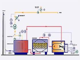
Under defined conditions, the catalytic thermal oxidizer (CTO) is an economical alternative for cleaning organic air pollutants (including VOCs). The system has proven to be particularly efficient when handling identifiable and consistent pollutant loads. In general, exhaust gases containing silicon and phosphorous cannot be treated. Under defined conditions, the Catalytic Thermal Oxidizer (CTO) is an economical alternative for cleaning organic air pollutants. The procedure is based upon the fact that under suitable conditions, even low amounts of volatile pollutants can be burnt without producing residue. This process would have required a high amount of heat energy. Therefore a catalyser and a heat exchanger are installed. The tubular heat exchanger installed behind the catalyser uses as much energy from the hot clean gases as possible in order to heat up the cold raw gases. The job of the catalyser is to decrease the amount of energy required to convert the pollutants without being depleted during the reaction. The raw gas loaded with pollutants is then forced into the heat exchangers of the CTO by the process fan. Here the raw gas is pre-heated by the hot clean gas. When required the burner heats up the exhaust gas further in the combustion chamber to the ignition temperature of the catalyser. In the catalyser the pollutants are converted into non-polluting CO2 and H20 vapour. After the catalyser, the clean gas is forced into the heat exchanger tubes. Along the way through the heat exchanger tubes the raw gases is heated and cooled. Eventually the clean gas leaves the system via the clean gas socket.

VENJAKOB MASCHINENBAU GMBH & CO KG
Germany
The regenerative thermal oxidizer from Venjakob Umwelttechnik with its low consumption of primary energy is particulary well suited to the removal of low to medium concentrations of solvend based pollutants (VOC). This machine is characterized by: The regenerative thermal oxidizer (RTO for short) embodies the state of the art technology for cleaning organic pollutants from exhaust gases (including VOCs). The systems ordinarily feature three alternately supplied heat exchanger chambers equipped with ceramic honeycombs. This material is suitable for absorbing, storing, and transferring very high amounts of heat. This allows a heat exchanger efficiency of over 95% to be achieved, so that the process temperature above 800 °C, which is required for the pollutant conversion, can be reached with a minimum of additional energy. Consequently, depending on the combustion heat of the pollutants to be cleaned, autothermal operation can be accomplished for most applications without the need for additional fuel. With careful planning, the excess heat of combustion can be effectively utilized so that the overall system can be viewed as an energy source rather than as an energy consumer. We can offer a variety of special solutions depending on the application:

VENJAKOB MASCHINENBAU GMBH & CO KG
Germany
The thermal incinerator (TI for short) is a system which converts gas or vaporous pollutants found in exhaust gas into non-polluting compounds by way of direct combustion. This machine is characterized by: The thermal incinerator (TI for short) is a proven and robust plant for the conversion of organic pollutants (VOCs, etc.). Today it is used especially for processes which involve high exposure to condensation or dust, or for specialized solutions requiring greater heat recovery potential. An example of this would be exhaust gases containing plasticizers or siloxane. The modular design of the combustion chamber and heat exchanger especially is conducive to servicing and cleaning compared to other designs. The polluted air is forced by means of a centrifugal fan into the tube bundle heat exchanger where it circulates around the tube bundle in a cross-current fashion. The heat exchanger can be designed for an efficiency of up to 70%. The pollutants are converted in the combustion chamber at a temperature of around 760 °C. After extensive heat transfer to the raw noxious gas, the cooled clean gas leaves the plant, where it can be supplied to various heat recovery systems (or a combination of several). The auxiliary burners can be operated with natural gas or propane or light heating oil.
Manufacturer/ Producer
Augsburger Straße 2-6
33378 Rheda-Wiedenbrück - Germany
europages also recommends
A selection of companies related to the activity:
A selection of products that might interest you
FÖHRENBACH GMBH
Germany

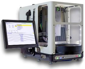
The machine structure with solid base plate is extremely compact and stable. All necessary components are integrated in the machine housing: mechanical axes, pneumatic components, control with drive electronics and mounted 12 "touch display. Depending on the desired version, the F-Décor 305 can produce surface patterns like circular grainings, côtes de Genève, engravings or decorative millings on mechanical watch parts. The machine guarantees high precision and high productivity. The F-Decor 305 is delivered ready for connection with either 1 or 2 working spindles.
J.D. GECK GMBH
Germany
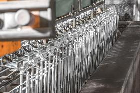
Use our industrial manufacturing expertise for your products too Electroplated surface finishing The maximum goods window for galvanising, chromeplating and nickelplating is L / W / D 2800x450x1000 mm. Chrome and nickel plating Galvanising (galvanising without passivation; blue galvanising with variable layer thickness and blue passivation; thicklayer passivation with nanosealing) Electrostatic powder coating Maximum load per hook 30 kg workpieces up to 60 kg Maximum workpiece size L / W / H = 3000/800 /1700 mm More information available at https//www.geck.de
Request for quotes
Create one request and get multiple quotes form verified suppliers.
- Only relevant suppliers
- Data privacy compliant
- 100% free