- europages
- >
- COMPANIES - SUPPLIERS - SERVICE PROVIDERS
- >
- linear potentiometers
Results for
Linear potentiometers - Import export

BURSTER PRÄZISIONSMESSTECHNIK GMBH & CO KG
Germany
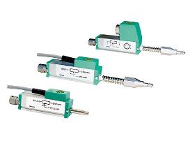
These displacement sensors are potentiometric displacement sensors used for direct measurement, testing and monitoring of mechanical displacements. The spring-loaded control rod eliminates the need of coupling with the measurement object. A prerequisite for a very long life duration of the devices is a parallel alignment of the motion direction of the measurement object and the rod. Areas of application are: Displacement on: —Electromagnets —Hydraulic cylinders —Switches and buttons Measurements of: —Deformation —Bending —Press-fits —Feed strokes Due to the technology employed in potentiometric displacement sensors, they always operate with a sliding contact system. FEATURES: —Measurement ranges: 0 ... 10 mm to 0 ... 150 mm —Non-linearity up to 0.05 % F.S. —Resolution 0.01 mm —Follower roll on request —Optional with internal spring
Request for a quote
BURSTER PRÄZISIONSMESSTECHNIK GMBH & CO KG
Germany
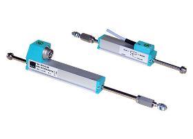
Displacement sensors models 8710 and 8711 with resistance tracks made of conductive plastic material are designed for a direct and accurate measuring of mechanical displacements. A special ball joint coupling is mountable on both ends of the driving rod. Because of this the sensor may be used free of clearance or lateral forces also with angular or parallel misalignment between sensor and measuring device. A special multi-fingered slider provides a good electrical contact also at high adjustment speeds or vibrations. Areas of application are: —Electromagnets —Switch and button deflections —Pneumatic cylinders —Press-fits (longitudinal press-fits) —Hydraulic cylinders —Measurements of deformation and bending —Length tolerances —Feeding paths Due to the technology employed in potentiometric displacement sensors, they always operate with a sliding contact system.
Request for a quote
BURSTER PRÄZISIONSMESSTECHNIK GMBH & CO KG
Germany
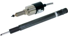
Linear displacements and mechanical values which can be converted to displacements (e.g. compressive and tensile force, strain, torque and vibration) may be measured by these DC/DC displacement sensors. The probe tip of these sensors is pushed onto the measuring object by a spring. This makes it possible to use these sensors were a mechanical modification of the measurement object (mounting hole) is not allowed or difficult. Output voltage as function of the displacement with the impedance as parameter. Sensors of series 87350 generally consist of an oscillator, a demodulator and a transformer with moveable core. They are energized by DC voltage. The oscillator uses this DC voltage to generate the carrier frequency, which is needed for the operation of the sensor. Dependent on the position of the core, which is made of ferromagnetic material, voltages are induced by the two secondary coils of the transformer.
Request for a quote
BURSTER PRÄZISIONSMESSTECHNIK GMBH & CO KG
Germany
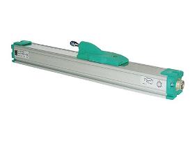
The high resolution allows linear measurements to be accurately sized even in large measurement ranges. Conversion of rotatory and translational motion by spindles, wires or others is not necessary for direct displacement measurement. Areas of application are: —Hydraulic and pneumatic cylinders —Detection of positions on coordinate —Inspection machines —Displacement of plungers, knee levers or extruders —Coil and de coil lengths —Strokes on chassis —Metering strokes Displacement sensors model 8718, using a resistance track made of conductive plastic material, are suitable for direct, accurate and absolute measurements of displacements and lengths. Special processes are applied to give the resistance tracks low friction, low tendency to stick/slip, resistance to abrasion and long-term stability. The vibration-cushioned slider allows a clear signal output even by slight shocks or high operating speeds up to 10 m/s.
Request for a quote
NOVOTECHNIK MESSWERTAUFNEHMER OHG
Germany
With the ever increasing automation of assembly lines, users are finding that values for absolute linearity are steadily gaining importance. Unlike independent linearity, for absolute linearity the reference slope is fully defined (Fig. 8) so that there is no need for subsequent system trimming. The definition of an index point establishes a relationship between the mechanical input value (travel or angle) and the output voltage. Potentiometers whose linearity is defined by these criteria can be installed without a need for subsequent adjustment. As with independent linearity, it is best to determine the absolute linearity of a potentiometer by comparing its output with that of a master potentiometer. With absolute linearity, it is frequently necessary for the tolerance fields to be stepped. Fig. 9 shows a practical example. Fig. 8 Fig. 9
Request for a quoteDo you sell or make similar products?
Sign up to europages and have your products listed

NOVOTECHNIK MESSWERTAUFNEHMER OHG
Germany
Smoothness is a measure of the deviations from perfect regularity that appear in the output voltage of a potentiometer. This irregularity is measured over a specified travel increment, for example 1 %, and is expressed as a percentage of the applied voltage. For the measurement of smoothness, the VRCI definition calls for a bandpass filter to be used as a means of suppressing any linearity error and for the potentiometer to be operated with a load resistance (e.g. 100 . Rp). This method has certain disadvantages: a) The use of a filter causes both the absolute wiper velocity and any changes in such velocity to affect the smoothness values. Since the filter partly integrates and partly differntiates, the chart-recorded smoothness curve does not accurately indicate the variations in the output signal. b) The load applied to the potentiometer also contributes to error by causing variation in the contact resistance which is greatest with the wiper at the voltage application end and...
Request for a quote
NOVOTECHNIK MESSWERTAUFNEHMER OHG
Germany
If a voltage U0 is applied to a potentiometer with a linear characteristic as in Fig. 5 and the wiper is moved in direction Alpha (standardized movement, angle 0;1 ) then the relationship illustrated in Fig. 6 will exist between the output voltage and the mechanically input value. The maximum deviation of the potentiometer curve from an ideal straight line is referred to as the independent linearity error. The slope and axis intercept of this straight line can be so chosen that the error f within the travel L1 is minimized. The error ±f is indicated as a deviation in percentage terms of the output voltage from the theoretical in relation to the input voltage. Since direct measurement of the potentiometer characteristic does not make it possible to assess the extent of such an error, only the difference between the potentiometer characteristic and that of an essentially perfect master potentiometer is plotted as in the practical example given in Fig. 7. Typical values for...
Request for a quote
NOVOTECHNIK MESSWERTAUFNEHMER OHG
Germany
Of all the quality features mentioned, linearity and conformity are the values most often defined in the existing literature (2). These terms express the extent to which the voltage output from a potentionmeter, and also other types of angular of linear movement sensor, differs from a prescribed theoretical function. In by far the majority of cases, the desired output function is directly proportional to the angel or linear movement that is input. Formula: Fig. 5. Whereby m characterizes the gradient, the offset voltage of the potentiometer and the linear or angular travel. Where there is a linear relationship, deviation is referred to as linearity. Where the relationship is nonlinear. U = f (x) + a + b the deviation is referred to as conformity. Fig. 5
Request for a quoteResults for
Linear potentiometers - Import exportNumber of results
9 ProductsCompany type
Category