
IGUS® GMBH
Germany

Universal adapter piece for cameras on our articulated arms With standard ball joint for connection to camera thread 1/4" UNC, with cable feedthrough for camera cable or power supply. Cables can be laid through the articulated arm. Weight with spherical head: 100 g Weight without spherical head: 50 g Material: Adapter: Fine grade polyamide PA2200 Ball head: Alumiium Universal adapter piece for cameras on our articulated arms With standard ball joint for connection to camera thread 1/4" UNC, with cable feedthrough for camera cable or power supply. Cables can be laid through the articulated arm. Weight with spherical head: 100 g Weight without spherical head: 50 g Material: Adapter: Fine grade polyamide PA2200 Ball head: Alumiium

IGUS® GMBH
Germany
Oscillatory robolink® joint - optional with angle sensors material: robolink® joint: Fine polyamide PA 2200 Screws: stainless steel VA Ropes:Dyneema Bearing: Alu HC(alternative iglidur® J) Balls: Oscillatory robolink® joint - optional with angle sensors material: robolink® joint: Fine polyamide PA 2200 Screws: stainless steel VA Ropes:Dyneema Bearing: Alu HC(alternative iglidur® J) Balls:

RK ROSE+KRIEGER GMBH
Germany
Ball joint monitor mounting Even more degrees of freedom through a ball joint socket Feature: max. load capacity 10 kg (static) 60° free swivelling reducing bushes available (round 20 and 25mm, square 20mm)

RK ROSE+KRIEGER GMBH
Germany
Four new models for even more flexibility The product family of aluminium Solid Clamp tube connectors has a new addition: size 30 base clamps, sleeve clamps and hinge clamps are now also available for delivery with integrated ball joint. A sleeve clamp with double ball also adds to the range. The ball joints are designed for loads of up to 40 Nm (static). Connected applications can be pivoted freely by 60° and rotated freely by 360°. This way, the new tube connectors with ball joint provide a significantly higher degree of freedom for construction than conventional hinged connectors. An appropriate surface coating on the ball joint makes for a high-strength clamping connection. The clamps feature a universal connecting plate for flexible integration. Features: can be combined with size 30 tube connectors the clamps feature a universal connecting plate (KGFS 30, KGM 30, KGGPZ 30) for flexible integration high-strength clamping thanks to special finishes
DURABLE HUNKE & JOCHHEIM GMBH & CO. KG
Germany
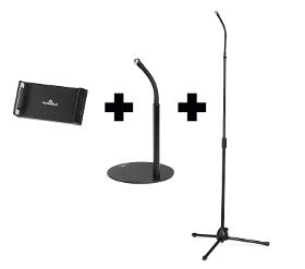
Tripod for tablets and cell phones from 4.7-13", flexible application as table or floor stand. Incl. carrying bag. • Table and floor stand with a tablet and cell phone holder, featured with flexible arm and ball joint • Suitable for all cell phones and tablets as well as iPad and iPhone from 4.7-13 inch up to 800g • Unlimited flexibility: depending on the application, the clamp can be mounted with the table or floor stand and thus offers endless application possibilities • Particularly ergonomic due to the flexible gooseneck which allows an individual and stepless height adjustment (360-degree rotation) • By using telescopic bar, the stand can be adjusted to any height up to 1.69m • Folded to 70 cm in the included carrying bag, the tripod is mobile and flexible to use • Non-slip pads in the clamp keep the tablet or cell phone stable and additionally protect against scratches • Cable management through integrated cable outlet in the clamp
SCHMITZ U. SÖHNE GMBH & CO. KG
Germany
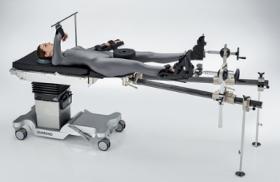
Seat section made of carbon fibre, with joint for inward swivelling. Incl. pad, 215 mm X-ray permeable, 360° radiolucent. Countertraction bar with padding, adjustable for RH or LH extension. Extension bars of carbon fibre, 1,400 mm long, 360° radiolucent. Each extension bar swivellling 45° outwards and 20° inwards. Extension slides made of aluminium, with mounting for the traction unit, height adjustable. Sliding traction unit infinitely adjustable on the bar, adjustable in all directions by ball-and-socket joint Incl. 2 supports, fixed to the bars by attachment clamps. Standard accessories: ----------------------------- 1 seat section, carbon fibre, with upholstery 2 extension bars, carbon fibre 2 extension bar supports, SST 2 extension shoes for adults 1 countertraction rod for supine position
TWK-ELEKTRONIK GMBH
Germany
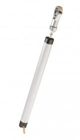
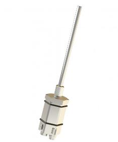
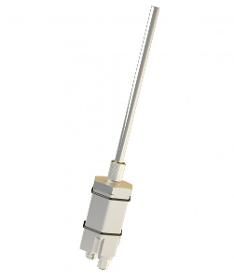
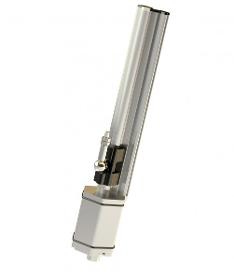
Cylindrical case in anodised aluminium - Shaft in stainlesssteel - Conductive plastic resistance elements - Precious-metal wipers - Axial connector or radial leads - Ball joints atshaft end and / or case at option - spring return (gauge) at option.
TWK-ELEKTRONIK GMBH
Germany
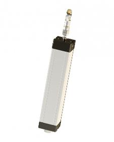
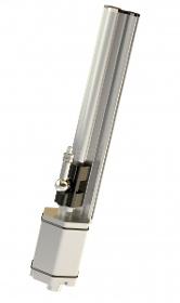
Rectangular case in anodised aluminium - Shaft in stainless steel - Shaft entry either with floating guidence against dust (AF) or with lip seal (AG) to protection grade IP 65 - Conductive plastic resistance elements - Precious metal wipers - Axial connector or axial or radial cable exit - Ball joints at shaft end and / or case on request.

TWK-ELEKTRONIK GMBH
Germany
The displacement transducers operate according to the principle of run time measurement between two points of a magnetostrictive waveguide. One point is determined by a moveable position magnet, whose distance from the null point corresponds to the section to be measured. The run time of an emitted impulse is directly proportionate to this section. Conversion to an analogue measuring signal takes place in the downstream electronics. The waveguide is housed in an extruded aluminium profile. The electronics is housed in a die-cast aluminium sensor head. Electrical connection is implemented via a circular connector. The position magnet is located either in a slider, which is linked to the moving part of the machine via a ball joint, or it moves as a liftable position magnet, without wear, over the profile.

TWK-ELEKTRONIK GMBH
Germany
The displacement transducers operate according to the principle of run time measurement between two points of a magnetostrictive waveguide. One point is determined by a moveable position magnet, whose distance from the null point corresponds to the section to be measured. The run time of an emitted impulse is directly proportionate to this section. Conversion to a measuring signal takes place in the downstream electronics. The waveguide is housed in a pressure-resistant stainless steel tube or extruded profile. To the rear of this is a die-cast aluminium housing containing the electronics in SMD technology. In the rod version, the position magnet is located in a ring, which is guided over the rod without contact. In the profile version, it is located either in a slider, which is linked to the moving part of the machine via a ball joint, or it moves as a liftable position magnet, without wear, over the profile.

TWK-ELEKTRONIK GMBH
Germany
The displacement transducers operate according to the principle of run time measurement between two points of a magnetostrictive waveguide. One point is determined by a moveable position magnet, whose distance from the null point corresponds to the section to be measured. The run time of an emitted impulse is directly proportionate to this section. Conversion to an analogue measuring signal takes place in the downstream electronics. The waveguide is housed in a pressure-resistant stainless steel tube or extruded profile. To the rear of this is a die-cast aluminium housing containing the electronics in SMD technology. Electrical connection is implemented via a circular connector. In the rod version, the position magnet is located in a ring, which is guided over the rod without contact. In the profile version, it is located either in a slider, which is linked to the moving part of the machine via a ball joint, or it moves as a liftable position magnet, without wear, over the profile.

TWK-ELEKTRONIK GMBH
Germany
The displacement transducers operate according to the principle of run time measurement between two points of a magnetostrictive waveguide. One point is determined by a moveable position ring, whose distance from the null point corresponds to the section to be measured. The run time of an emitted impulse is directly proportionate to this section. Conversion to a displacement signal takes place in the downstream electronics. The waveguide is housed in a pressure-resistant stainless steel tube or extruded profile. To the rear of this is a die-cast aluminium housing containing the electronics in SMD technology. In the rod version, the position magnet is located in a ring, which is guided over the rod without contact. In the profile version, it is located either in a slider, which is linked to the moving part of the machine via a ball joint, or it moves as a liftable position magnet, without wear, over the profile.
TWK-ELEKTRONIK GMBH
Germany
The displacement transducers operate according to the principle of run time measurement between two points of a magnetostrictive waveguide. One point is determined by a moveable position magnet, whose distance from the null point corresponds to the section to be measured. The run time of an emitted impulse is directly proportionate to this section. Conversion to a digital measuring signal takes place in the downstream electronics. The waveguide is housed in a pressure-resistant stainless steel tube or extruded profile. To the rear of this is a die-cast aluminium housing containing the electronics in SMD technology. In the rod version, the position magnet is located in a ring, which is guided over the rod without contact. In the profile version, it is located either in a slider, which is linked to the moving part of the machine via a ball joint, or it moves as a liftable position magnet, without wear, over the profile.
TWK-ELEKTRONIK GMBH
Germany
The displacement transducers operate according to the principle of run time measurement between two points of a magnetostrictive waveguide. One point is determined by a moveable position ring, whose distance from the null point corresponds to the section to be measured. The run time of an emitted impulse is directly proportionate to this section. Conversion to a displacement signal takes place in the downstream electronics. The waveguide is housed in a pressure-resistant stainless steel tube or extruded profile. To the rear of this is a die-cast aluminium housing containing the electronics in SMD technology. In the rod version, the position magnet is located in a ring, which is guided over the rod without contact. In the profile version, it is located either in a slider, which is linked to the moving part of the machine via a ball joint, or it moves as a liftable position magnet, without wear, over the profile.

TWK-ELEKTRONIK GMBH
Germany
The linear transducer model PWA measures the absolute position of the plunger without contact or wear using an inductive resonator measuring system. This consists of an excitation coil which causes an oscillating resonance circuit (moving target) fastened to the plunger to oscillate. This in turn excites the receiver coils fixed in the housing, which are printed on a printed circuit board. The integrated electronics transform these signals (sin/cos) into a signal proportionate to the linear travel. The measuring system is insensitive to electrical and magnetic fields. 0(4) to 20 mA and 0 to 10 VDC are available as standard as analogue signal outputs. CANopen, IO link and SSI are in preparation. The sensor is fastened using at least two retaining clips HK-01 or using sliding blocks ST-01. The sensor can be equipped with ball joints at the front and rear. Alternatively, the sensor's plunger can be designed as a button.

TWK-ELEKTRONIK GMBH
Germany
The displacement transducers operate according to the principle of run time measurement between two points of a magnetostrictive waveguide. One point is determined by a moveable position magnet, whose distance from the null point corresponds to the section to be measured. The run time of an emitted impulse is directly proportionate to this section. Conversion to an analogue measuring signal takes place in the downstream electronics. The waveguide is housed in a pressure-resistant stainless steel tube or extruded profile. To the rear of this is a die-cast aluminium housing containing the electronics in SMD technology. Electrical connection is implemented via a circular connector. In the rod version, the position magnet is located in a ring, which is guided over the rod without contact. In the profile version, it is located either in a slider, which is linked to the moving part of the machine via a ball joint, or it moves as a liftable position magnet, without wear, over the profile.

Do you sell or make similar products?
Sign up to europages and have your products listed

TWK-ELEKTRONIK GMBH
Germany
The displacement transducers operate according to the principle of run time measurement between two points of a magnetostrictive waveguide. One point is determined by a moveable position magnet, whose distance from the null point corresponds to the section to be measured. The run time of an emitted impulse is directly proportionate to this section. Conversion to a digital measuring signal takes place in the downstream electronics. The waveguide is housed in a pressure-resistant stainless steel tube or extruded profile. To the rear of this is a die-cast aluminium housing containing the electronics in SMD technology. Electrical connection is implemented via a circular connector. In the rod version, the position magnet is located in a ring, which is guided over the rod without contact. In the profile version, it is located either in a slider, which is linked to the moving part of the machine via a ball joint, or it moves as a liftable position magnet, without wear, over the profile
TWK-ELEKTRONIK GMBH
Germany
The displacement transducers operate according to the principle of run time measurement between two points of a magnetostrictive waveguide. One point is determined by a moveable position magnet, whose distance from the null point corresponds to the section to be measured. The run time of an emitted impulse is directly proportionate to this section. Conversion to a digital measuring signal takes place in the downstream electronics. The waveguide is housed in a pressure-resistant stainless steel tube or extruded profile. To the rear of this is a die-cast aluminium housing containing the electronics in SMD technology. Electrical connection is implemented via a circular connector. In the rod version, the position magnet is located in a ring, which is guided over the rod without contact. In the profile version, it is located either in a slider, which is linked to the moving part of the machine via a ball joint, or it moves as a liftable position magnet, without wear, over the profile.

TWK-ELEKTRONIK GMBH
Germany
The displacement transducers operate according to the principle of run time measurement between two points of a magnetostrictive waveguide. One point is determined by a moveable position magnet, whose distance from the null point corresponds to the section to be measured. The run time of an emitted impulse is directly proportionate to this section. Conversion to an analogue measuring signal takes place in the downstream electronics. The waveguide is housed in a pressure-resistant stainless steel tube or extruded profile. To the rear of this is a die-cast aluminium housing containing the electronics in SMD technology. Electrical connection is implemented via a circular connector. In the rod version, the position magnet is located in a ring, which is guided over the rod without contact. In the profile version, it is located either in a slider, which is linked to the moving part of the machine via a ball joint, or it moves as a liftable position magnet, without wear, over the profile.

FTK FÖRDERBAND TECHNIK KILIAN GMBH
Germany
Regular rollers prevent belt misalignment and guarantee protection of the belt edges. As the regular rollers only function efficiently when the drum casing is clean, the rollers are equipped and delivered with dirt repellent 60° shore soft rubber. Our regular rollers can be used with both normal and reversing conveyor belts. Mode of operation When the conveyor belt is running straight, the axle through the roller casing forms an angle of 90° to the direction of movement of the belt. When the belt drifts, the roller casing moves, due to the dead weight of the belt, so that a forward motion occurs which brings the belt back to its normal position. The roller casing returns to its normal position as soon as the corrective procedure is completed. The mechanics of the movement are rendered possible due to a complex ball joint in the centre of the roller as well as the position of the axle in relation to the conveyor belt being less than 90°.
FTK FÖRDERBAND TECHNIK KILIAN GMBH
Germany
The carrying frame prevents belt misalignment and guarantees protection of the belt edges. As the carrying frames only function efficiently when the drum casing is clean, they are equipped and delivered with dirt repellent 60° shore soft rubber. Our carrying frames can be used with both normal and reversing conveyor belts. Mode of operation When the conveyor belt is running straight, the axle through the roller casing forms an angle of 90° to the direction of movement of the belt. When the belt drifts, the roller casing moves, due to the dead weight of the belt, so that a forward motion occurs which brings the belt back to its normal position. The roller casing returns to its normal position as soon as the corrective procedure is completed. The mechanics of the movement are rendered possible due to a complex ball joint in the centre of the roller as well as the position of the axle in relation to the conveyor belt being less than 90°.
Results for
Ball joints - Import exportNumber of results
24 Products