

NORELEM FRANCE
France

Housing polyamide 6. Hollow shaft steel. Screen plastic. Grub screw steel. Version Impactresistant housing. Hollow shaft black oxidised. Grub screw black. Dial black, digits white. Note Position indicators allow direct reading of input measurement values at a glance. In addition, the value indicated per spindle rotation (corresponding spindle pitch) can be selected and the various indicator values are realised by a transmission gear. The position indicators are distinguished by their small construction with very clear display. They are especially suitable for small spindle distances and small shaft diameters and have a torque support that is positioned in a hole on the side. ** At the 1st asterisk give assembly position and at the 2nd asterisk give the count direction (see sample order “assembly position, count direction”). Technical data – Counter consisting of 3 10position dials – Height of figures about 4 mm – Hollow shaft Ø 10 H7 mm

NORELEM FRANCE
France
Body and rotary table Al alloy, anodised. Spindle steel, casehardened. Spindle bearing maintenancefree. Position indicator plastic. Version Radial play of rotation axis < 0.015 mm. Axial play of rotation axis < 0.02 mm. Repeat accuracy < 0.05°. Spindle selflocking. Note 360° adjustment with no end stop. The position indicator displays in 0.1° increments clockwise. The angle of rotation is indicated directly on the large LCD display. The rotary stage rotates anticlockwise. Reset, chain dimension and offset settings can be made via the keypad. 2 years battery life. The battery is quick and easy to replace. The mounting position of the position indicator is set in 4 positions using one screw. Transmission ratio 211611008 = 501 211611012 = 551 211611025 = 501 The modular design enables the rotary stage to be easily combined with other items of the same size. Drawing reference Assembly position of position indicator a) top (standard) b) right c) bottom
NORELEM FRANCE
France
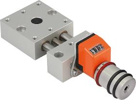
Bearing block and carriage aluminium alloy, anodised. Guide columns stainless steel, ground. Spindle stainless steel, rolled thread. Guide bearing maintenancefree. Position indicator plastic. Version Radial play on guide < 0.02 mm. No axial backlash. Spindle selflocking, with additional lock. Note Due to the practically playfree guides and absolutely playfree spindle, loosening or clamping of the spindle is not required during adjustments. Digital position indicators with 0.1 mm display accuracy, digits increase with right rotation. The display value of the position indicator can be adjusted by turning the carrier ring. The mounted position of the position indicator can be set in 4 positions with a screw. Within the respective sizes, the positioning stages can be easily combined using the modular principle. Drawing reference Assembly position of position indicator a) top (standard) b) right c) bottom d) left
NORELEM FRANCE
France
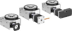
Base and rotary table aluminium alloy. Hollow shaft stainless steel. Preloaded worm gear steel. Claw coupling aluminium with polyurethane coupling spider. Version Aluminium alloy anodised. Note for ordering The unit is supplied with the position of cable outlet or control unit as shown in the drawing. Note Rotary positioning stages for motorised adjustment and positioning tasks. The preloaded worm gear runs virtually playfree. The bearing of the worm shaft offers maximum radial rotational accuracy. Cables can be routed through the large bore in the hollow shaft. The adjustable positioning ring is used to determine the rotational reference point to the position of the assembled part. Proximity switches can be mounted with the optionally available sensor holder (21094). The suitable programming software and interface cable for the stepper motor with positioning control are available as accessories (2500015).
NORELEM FRANCE
France
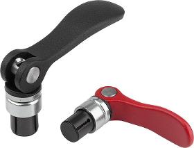
It is recommended that the cam lever is in a vertical position when the collet is positioned in the bore. The function of the clamping system was tested in bores with tolerance H7. All values for retaining force are guide values and are given without safety factor. The suitability for the respective application must be checked by the user. Advantages: Two components can be joined together without tools. The components are perfectly centred in the clamped state. The compact design means that the mandrel collet with cam lever can even be used in blind holes. There are no specific dimensional requirements for the holes. Additionally, the surfaces and design do not need to have any specific properties. Functional principle: The clamping system is inserted in the hole in the open state. At the beginning of the locking process, the mandrel collet expands and clamps itself in the lower component. The integrated disc spring assembly creates a positive down force

Do you sell or make similar products?
Sign up to europages and have your products listed

PATRY
France
Series 1000 Series 2000 Series 2100 Series 5100 SINGLE WELDED CLIP, SERIES 1000 - 5000 Welded clips, supplied with bolts CLIP VALEX 1004 SERIES 1000 TECHNICAL SPECIFICATIONS: • Lateral adjustment 7 mm • Lateral load of 60 KN • Tightening torque 175 Nm Use: The Valex series 1000 direct fastening system is intended for rails of the overhead crane type. It is very robust, reliable and occupies little space. It can be used for the tracks of any type of crane. CHARACTERISTICS: • Elastic fastening of the rails, with or without pad. • System consisting of two elements, permitting simple lateral adjustment of the rail. • Easy maintenance; the elastomeric nose fixed on the point where the clip presses on the rail increases the rail-support tolerances, reduces the forces on the fastenings and guarantees better retention of the rail. ASSEMBLY INSTRUCTIONS: Align the rails. Position the clips on the rail, then the washers. Insert the bolt and proceed to tighten. Check the alignment of...
Results for
Assembly position - Import exportNumber of results
7 ProductsCountries
Company type