Rotary encoder TBA50
Absolute rotary encoder with Hall elements and interface Electronics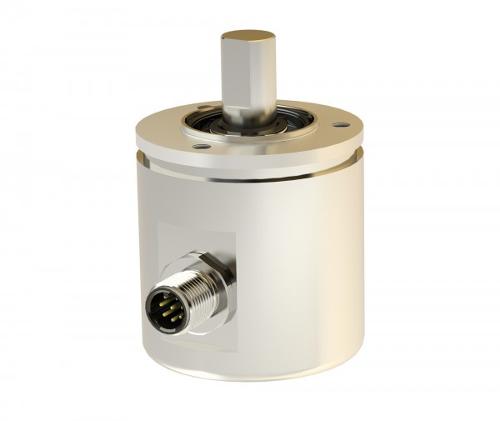
Description
Robust case with wall thickness of 5 mm either in seawater resistant aluminum or in stainless steel - shaft and ball bearings in stainless steel - rotating components with permanent magnet in front chamber - electronic circuit with ASiC and Hall elements and interface components fitted within main chamber, separated from rotating components by a metallic wall - optional potting against water jets (IP 69K) - electrical connections via round plug or lead exit.
- Potentiometers
- sensor
- potentiometer
- absolute encoder
Product characteristics
- Inkremental or absolute
- Absolute
- Interface
- Analogue
- Single- or Multiturn
- Singleturn
- Design
- 50mm
- Housing material
- Aluminium, Stainless steel
- Flange and shaft
- Synchroniser flange
- Measuring range
- 360°
- Signal path
- CCW (optional), CW
- Electrical connection
- Cable 1m, Device connector M12 x 1
- Output signal analogue
- 0 to 10VDC, 0 to 20 mA, 4 to 20 mA, ± 10VDC
Documents
Similar products
BURSTER PRÄZISIONSMESSTECHNIK GMBH & CO KG
Germany

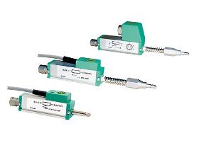
These displacement sensors are potentiometric displacement sensors used for direct measurement, testing and monitoring of mechanical displacements. The spring-loaded control rod eliminates the need of coupling with the measurement object. A prerequisite for a very long life duration of the devices is a parallel alignment of the motion direction of the measurement object and the rod. Areas of application are: Displacement on: —Electromagnets —Hydraulic cylinders —Switches and buttons Measurements of: —Deformation —Bending —Press-fits —Feed strokes Due to the technology employed in potentiometric displacement sensors, they always operate with a sliding contact system. FEATURES: —Measurement ranges: 0 ... 10 mm to 0 ... 150 mm —Non-linearity up to 0.05 % F.S. —Resolution 0.01 mm —Follower roll on request —Optional with internal spring
SIKO GMBH
Germany
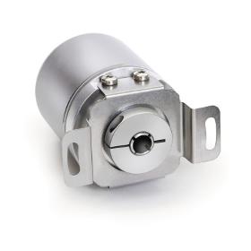
The AH36M rotary encoder with teach-in function is a magnetic absolute value encoder with analog output. The user himself can set the rotary encoder's desired measurement range via two external inputs. The device features a batteryless multi-turn technology. Absolute analog encoder. 12 Bit (4096) resoluttion over the measuring range. Operating tmperature until -40 °C. Voltage (0 … 10 V)/ current (4 … 20 mA) outputs. Programmable measuring range via teach-in function with external inputs. Hollow shaft with ø6 mm.

NOVOTECHNIK MESSWERTAUFNEHMER OHG
Germany
If there is axial misalignment (eccentricity) between the drive shaft and the shaft of a potentiometer used to sense angular, motion, this will cause a linearity error that increases as the coupling radius decreases in relation to the degree of eccentricity. The following equation determines the maximum relative error Fmax = E/Pi · rk where E = Eccentricity und rk = the coupling radius. It is only possible to take full advantage of the linearity or conformity of any rotationary sensor system, if coupling alignment errors (offset and angular misalignment) are avoided or at least reduced to a mimimum. This means that with highly accurate measurement systems, due allowance must be made for any coupling misalingment in accordance with the above equation.

ELAP AUTOMAZIONE INDUSTRIALE
Italy
Thanks to their small size – 21 mm square section case – the linear potentiometers seris PT2S can be profitably employed for those applications where limited dimensions are a critical factor. Two ball joints are provided at both ends for air fixing. The series strokes range from 25 to 150 mm. The electrical connection is granted by means of M12 connector. The stout extrused aluminium case grants a high protection degree against environmental agents.
Request for quotes
Create one request and get multiple quotes form verified suppliers.
- Only relevant suppliers
- Data privacy compliant
- 100% free